Heat Exchangers are critical components in industrial systems where temperature control is essential. From chemical processing plants and oil refineries to HVAC systems and power stations, proper heat transfer calculation ensures efficiency, safety, and cost-effectiveness.
In this blog, we will clearly explain how heat transfer is calculated in Heat Exchangers, the formulas used, important design parameters, and why accurate calculation matters in industrial applications.
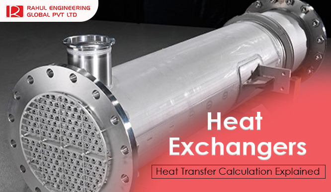
What Are Heat Exchangers?
Heat Exchangers are devices designed to transfer heat between two fluids without allowing them to mix. One fluid releases heat (hot fluid), while the other absorbs it (cold fluid).
They are widely used in:
- •Chemical industries
- •Power generation plants
- •Oil & gas refineries
- •Food processing units
- •Pharmaceutical manufacturing
- •HVAC systems
Basic Heat Transfer Concept
Heat transfer in Heat Exchangers mainly occurs through:
- 1. Conduction – Heat transfer through the metal wall separating fluids
2. Convection – Heat transfer between fluid and metal surface
3. Radiation – Minor contribution in most industrial exchangers
The total heat transferred depends on fluid properties, temperature difference, and surface area.
The simplest formula used to calculate heat transfer is:
Q = m × Cp × ΔT
Where:
This equation helps determine how much heat is removed or added to a fluid.
For real industrial design, engineers use:
Q = U × A × ΔTlm
Where:
This equation is used in designing shell & tube and plate Heat Exchangers.
Temperature difference changes along the length of the Heat Exchanger. To calculate an average value, engineers use LMTD.
LMTD provides more accurate thermal design compared to simple temperature difference.
Counterflow Heat Exchangers usually have higher LMTD, making them more efficient than parallel flow systems.
Heat Exchangers operate in:
Counterblow design generally offers better thermal efficiency.
The U-value depends on:
Higher U-value means better heat transfer performance.
Larger heat transfer area increases efficiency. Manufacturers increase area by:
Deposits like scale, dirt, or corrosion reduce heat transfer efficiency. Engineers include a fouling factor in calculations to ensure long-term performance.
Example Heat Transfer Calculation
Suppose:
Using formula:
This means the Heat Exchanger transfers 188.1 kW of heat energy.
When outlet temperatures are unknown, engineers use the NTU (Number of Transfer Units) method.
This method is useful for:
It calculates heat transfer based on effectiveness and capacity ratio.
Heat Exchanger thermal calculations follow international standards such as:
These standards ensure safety, reliability, and performance in industrial applications.
Proper heat transfer calculation ensures:
Incorrect calculations can result in undersized equipment, overheating, pressure drops, and higher maintenance costs.
Heat Exchangers: Heat Transfer Calculation Explained helps industries understand the science behind efficient thermal design. By applying formulas like Q = mCpΔT and Q = UAΔTlm, engineers can optimize performance and ensure reliable operation.
Accurate heat transfer calculations are essential for maximizing efficiency, reducing energy consumption, and improving overall industrial productivity.